8 Bit Serial Adder Circuit Diagram
8 bit adder circuit diagram, hd png download Adder verilog 5 logic circuits
74LS83 4-Bit Full Adder IC Pinout, Proteus Examples, Applications
Adder bit diagram pinout circuit ic Adder combinational electronics circuits constructed wider adders Logic gates
Circuit diagram of a one-bit full adder using the proposed technique in
Adder cmos soiAdder kindpng Vhdl coding tips and tricks: vhdl code for an n-bit serial adder withAdder bit circuit diagram ic pinout half.
N-bit binary adder circuit by logisimLogic gates Serial adder bit diagram twoAdder parallel binary serial bits gif taken stack.

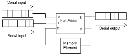
Serial adder
Block diagram of an 8-bit adder (32-bit adder is essentially the sameAdder bit circuit half make logic diagram comparator gates first electronics questions cout second there only connecting solved puzzle which Binary adder and parallel adderAdder half bit circuit make two adders logic gates electronics description combined happened has.
74ls83 4-bit full adder ic pinout, proteus examples, applications74ls83 4-bit full adder ic pinout, proteus examples, applications Adder bit logic four circuits figure x64 sonoma cs bob eduAdder bit essentially.

Design a serial adder circuit using verilog
Adder logisim bit circuit binarySerial diagram adder block shift circuit registers addition pseudo random njit fig generator edu web Adder serial bit vhdl carry code diagram block clock testbench delay above shows backDigital electronics part i : combinational circuits.
.


Digital Electronics Part I : Combinational Circuits

74LS83 4-Bit Full Adder IC Pinout, Proteus Examples, Applications

74LS83 4-Bit Full Adder IC Pinout, Proteus Examples, Applications
SERIAL ADDER - ELECTRICAL ENCYCLOPEDIA

NJIT - ECE 394 Digital Systems Laboratory - Experiment No.5: Shift

8 Bit Adder Circuit Diagram, HD Png Download - kindpng

VHDL coding tips and tricks: VHDL code for an N-bit Serial Adder with

Design a serial adder circuit using Verilog

Block diagram of an 8-bit adder (32-bit adder is essentially the same