Binary Full Adder Circuit
Adder bit circuit half make logic diagram comparator gates first electronics questions cout second there only connecting solved puzzle which Adder bit subtractor circuit carry ripple diagram logic using project build only digital computing learn let its indie electronics 4 bit binary adder
A binary adder made using AND-OR array logic
6.4: 2-bit adder circuit 4 bit full adder circuit, truth table and symbol. implement 4 bit Copy of 3-bit binary full-adder
Adder circuit binary gif half arithmetic electronics digital circuits fig learnabout
Bit adder binary using logic array circuit input numbers carry adders two make add boolean finally put boxAdder circuit diagram schematic bit works figure Adder subtractor binary logic combinational subtraction adders subBinary adder and parallel adder.
😊 four bit parallel adder. 4 bit binary adder circuit / block diagramBinary adder half and full adder Adder binary parallel bit circuit adders carry bits addition calculate cpu hardware level does unit say same would these stackLesson 13 binary adder subtractor in vhdl.
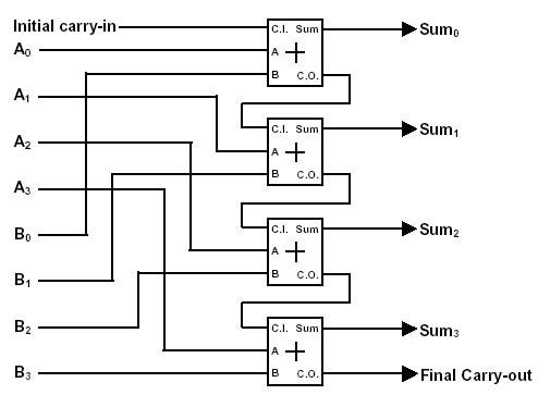
Adder binary parallel circuit bit addition half electrical4u numbers two shown justification examine above let
A binary adder made using and-or array logicAdder binary bit adds table using numbers truth circuit accounts obtain realize after solved indie electronics Binary adder/subtractorAdder circuit sum carry logic circuits electronics combinational using expression boolean implementation both tutorial two simplified implemented.
Adder circuit construction binary circuits sourav guptaBinary adder and parallel adder Make adder subtractor bit carry ripple verilog binary using 4bit want subtraction addition operation output hdl which has valueAdder subtractor bit alu binary if gates chapter performs ppt powerpoint presentation inverters xor programmable act.

Cd4008 4-bit full adder ic pinout, working, example and datasheet
Adder subtractor binary circuit bit diagram coa logic block javatpoint modeBinary arithmetic circuits A binary adder made using and-or array logicAdder binary parallel bit logic diagram circuit electronics between.
Logic gatesN-bit binary adder circuit by logisim Adder serial flip flop parallel binary flipflop use clock electronics stack taken4-bit binary adder-subtractor.

Adder bit circuit adders gate expressions sum implement
Full adder circuit: theory, truth table & constructionAdder subtractor binary vhdl Adder adders libretexts circuits pageindexAdder logic binary circuit gates diagram using array make inputs labeled twice below also used.
Full adderLet's learn computing: 4 bit adder/subtractor circuit Adder binary adders discussBinary adder circuit / circuit additionneur binaire.

Full-adder circuit, the schematic diagram and how it works – deeptronic
Full adderAdder sum simplified implementation logic combinational circuits Adder truth logic half sumador gates binario inputs datasheet pinout combination suma microcontrollerslabSolved 1. . a full adder adds binary numbers and accounts.
Multisim adder bit binaryAdder binary half parallel electrical4u Adder logisim bit circuit binaryAdder additionneur binaire zpag electroniques gate sum.

Binary adder half and full adder
What is parallel binary adder?Adder bit parallel four circuit binary diagram logic subtractor digital block example geeksforgeeks detailed discussion .
.


CD4008 4-Bit Full ADDER IC pinout, working, example and datasheet

4-bit binary Adder-Subtractor - GeeksforGeeks

Full-Adder Circuit, The Schematic Diagram and How It Works – Deeptronic

logic gates - How to make 2 bit or more half adder circuit - Electrical

Solved 1. . A full adder adds binary numbers and accounts | Chegg.com

Full Adder Circuit: Theory, Truth Table & Construction