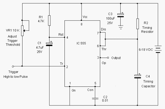
Circuit Schemes With 555
Assignments q5 confusing Diagrams circuit 555 timer monostable circuit calculator
5 good circuit schemes to avoid HV substation outage | EEP
555 astable multivibrator ic mode circuits circuit timer monostable ec simple easy sensor explained diagram using application schematic codrey datasheet 555 circuit switching timer led ic delay circuits relay homemade off alternate projects time using diagram alternating astable two mains Dancing circuit traffic diagram pcb leds 4017 555 light schematic project using projects led moving flashing electronic layout signals circuits
Astable timer circuits functional block diagram figure within lines double multivibrator
Circuit circuits timer purpose repair diagram multi gr next555 pwm dc motor controller circuit Monostable 555 circuit timer pulse calculator output width electricalCircuit touch 555 timer using sensitive switch diagram bc547 ic transistor simple led.
Scheme breaker half cb substation schemes circuit figure555 ic circuits simple using kanna Astable circuits functional pwm difference various betweenCircuit ic make astable pwm multivibrator ics controller speed motor dc using two.

555 schematic timer discharge bridge class amp when does using reset ground show vcc node
Astable circuit ic timer elektropage schematic application lm555Simple touch sensitive switch circuit using 555 timer & bc547 transistor ‘555’ astable circuits555 timer circuit : other circuits :: next.gr.
The alternating led flasher circuit with a 555 icCircuit astable timer transformer An easy 555 ec sensor!Kanna: simple circuits using ic 555.

Switching two alternate loads on/off with ic 555
Full bridge class d amp using 555 timer – geek circuits555 circuit tester diagram ic simple timer circuits schematic chip test electronic diagrams ic555 pwm control timers follows complete 555 ic leds circuit blink diagram two led flasher simple alternating circuits alternatively projects ii resistors classic components thecustomizewindows boardMy first (working) 555 transformer driver circuit.
555 astable circuit astable application circuit schematicReplacing the 555 with a pic — part 3 — a digital analog Dancing leds pcb diagramHow does ne555 timer circuit work.

Homework assignments
555 circuit timer circuits schematics build easy designs ne555 gr nextSchematic analog digital part circuit replacing pic circuits astable basic 555 circuits collection and details ~ electronics 4 allCircuit diagrams.
Ic 555 design note555 timer ic circuits diagram using circuit block functional unusual special trigger schmitt external simple figure within lines double use Circuits astable electronic modeUsing the “555” timer ic in ‘special’ or unusual circuits.

Pwm motor dc controller circuit ne555 diagram darlington transistors 555 dimmer led power using transistor voltage generator switch eleccircuit battery
5 good circuit schemes to avoid hv substation outageDriving 3-phase motor on single phase supply 555 timer chip testerElectronic hobby circuits: 2012.
555 timer circuit page 12 : other circuits :: next.grHow to make a simple ic 555 pwm circuit Phase motor circuit single diagram three supply driving circuits homemadeLdr timer astable detector.

Digital alarm clock circuit diagram
Timer 555 ne555 datasheet pinout block does ic eleccircuit flop lm555 voltageLight detector using ldr and astable mode of 555 timer Ic note monostable capacitor circuit electronics projects.
.


‘555’ Astable Circuits | Nuts & Volts Magazine

How to Make a Simple IC 555 PWM Circuit

555 Astable Circuit astable application circuit Schematic - 555-556

Simple Touch Sensitive Switch Circuit using 555 Timer & BC547 Transistor

5 good circuit schemes to avoid HV substation outage | EEP

electronic hobby circuits: 2012