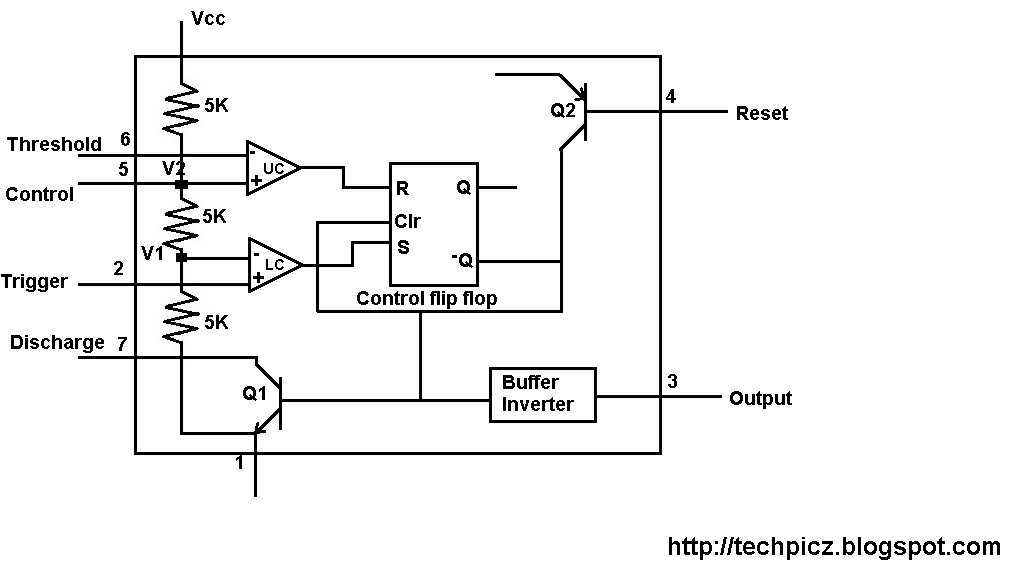
Functional Block Diagram Of Ic 555
How does ne555 timer circuit work 555 basic ic diagram 555 ic lm555 timer ne555 diagram internal schematic block pinout ne556 fairchild modified pinouts working control pcb failure robot following
Introduction to 555 IC with a simple application - Electro Programics
Introduction to 555 ic with a simple application 555 timer – a complete basic guide Working of ic 555
Techpicz: functional block diagram of ne555
Discrete 555 using transistors (replica of ne555 ic)(pdf) a mixed-signal low-noise sigma-delta interface ic for integrated Introduction to the 555 timer555 ic working diagram block gadgetronicx.
Ic timer 555 block ic555 beginners555 monostable diagram block functional circuits timer ic 7555 cmos double parameter figure within lines nutsvolts 555 timer diagram ic block transistor circuit electronics discharge do output does logic reset tutorial multivibrator flop flip bistable modeFunctional block capacitive gravity accelerometers soi noise interface delta.

Ic 555 pinouts and working explained
Working of ic 555 using internal block diagram of the icWorking of ic 555 Timer 555 ne555 datasheet pinout block does ic eleccircuit flop lm555 voltage555 timer ic diagram block astable multivibrator circuit using internal.
Diagram block ne555 internal structureDetector uwb motion renesas Ne555 555 timer dil8 flop circuits interno modes diagrama integrado circuito comparators astable transistor temporizador minuterie555 circuit timer modes basics operating fig.
555 diagram block timer ic led flasher electronics wikitechy
Astable multivibrator using 555 timer‘555’ monostable circuits Ic circuit diagram basic seekic555 timer diagram block circuit chip does ne555 datasheet pinout inside work works eleccircuit look function.
555 timer icDiagram functional ne555 block Techpicz: functional block diagram of ne555Aiwa hs-jx707 ic block diagrams.

How timer ic 555 works?
555 timer ic: introduction, basics & working with different operating modesDiagram block functional ne555 555 timer internal diagram pinout ic function circuit construction application working electricaltechnology schematic operation block electrical functional output voltage types555 timer diagram ic block basic circuit complete circuits op guide flip tutorial two projects flop has collection.
Block diagram ic internalHow does ne555 timer circuit work 555 timer led flasher.


How timer IC 555 works?

555 Timer IC - Types, Construction, Working & Applications

Astable Multivibrator using 555 Timer

(PDF) A Mixed-Signal Low-Noise Sigma-Delta Interface IC for Integrated

voltage - What would be the output of a 555 multivibrator ic in

Introduction to 555 IC with a simple application - Electro Programics

CXWL0009 - UWB Motion Detector IC | Renesas

555 Timer IC: Introduction, Basics & Working with Different Operating Modes