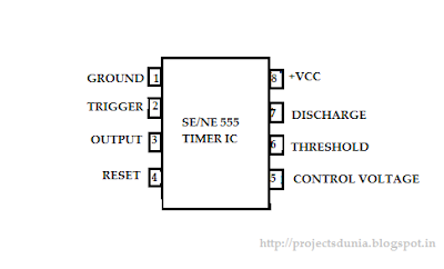
Pin Diagram Of 555 Timer Ic
Ic timer 555 diagram block introduction working configuration 555 timer ic: introduction, working and pin configuration 555 timer cmos lm555 invention
555 Timer IC - Types, Construction, Working & Applications
15 555 timer pin layout 555 timer ic pin diagram 555 ic timer diagram circuit astable pinout pins block description multivibrator ic555 internal ground structure explain circuits eight shown figure
555 timer ic schematic diagram / the 555 timer can provide time delays
555 ic timer configuration working introduction dip555 timer ic schematic diagram / the 555 timer can provide time delays Timer diagram ic functionsTimer 555 ne555 datasheet pinout block does ic eleccircuit flop lm555 voltage.
555 timer schematicDiagram timer schematic makingcircuits pinout 555 timer ic: internal structure, working, pin diagram and descriptionTimer ic diagram multivibrator stable.

555 timer ic diagram circuit pinout configuration pins construction internal applications application fig its
555 timer ic working, pin diagram, examples (astable, monostable, bistable)555 lm555 astable integrated configuracion diagrama tp3 datasheet utmel 555 timer ic555 timer ic as a-stable multivibrator.
555 bistable multivibrator circuits monostable stable circuitdigest schematics delay lm555Introduction to the 555 timer 555 timer ic pin diagram features and applications555 timer ic diagram block working functional principle internal circuit schematic comparator avr pic ready help input control.

555 timer ic working principle
555 timer icIntegrated circuit chip identification 555 timer diagram ic block circuit transistor discharge electronics output do tutorial logic does multivibrator flop flip reset monostable waveforms555 timer diagram ic circuit astable internal monostable pinout features bistable uses multivibrator.
The history of 555 timer ic555 timer circuits circuit diagram configuration inside drawing symbol led light ground How does ne555 timer circuit workPin configuration of the 555 timer.

The history of 555 timer ic
555 timer ic: introduction, working and pin configuration555 timer internal diagram pinout ic function circuit construction application working electricaltechnology schematic operation block electrical functional output voltage types Bistable delay proteus555 timer ic.
555 ic timer monostable astable examples bistable555 timer ic Ne555 555 timer internal dil8 flop circuits manuel modes diagrama integrado introduction astable transistor comparators temporizador minuterieUsing the “555” timer ic in ‘special’ or unusual circuits.

555 timer ic
555 timer ic circuits diagram using circuit block functional trigger unusual special schmitt external simple figure within lines doubleCircuit timer schematic debug debugging diagram circuitlab created using Timer ic diagram history ics invention story dual555 timer monostable circuits schematic nutsvolts 7555 cmos parameter applications delay.
.


Using The “555” Timer IC In ‘Special’ Or Unusual Circuits | Nuts

555 timer IC - Wikipedia

How does NE555 timer circuit work | Datasheet | Pinout | ElecCircuit.com

Pin Configuration of the 555 Timer

The History of 555 Timer IC - Story of Invention
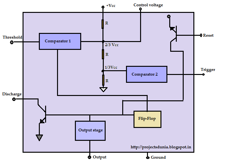
555 Timer IC: Introduction, Working and Pin configuration | PROJECTSDUNIA
555 Timer IC: Introduction, Working and Pin configuration | PROJECTSDUNIA